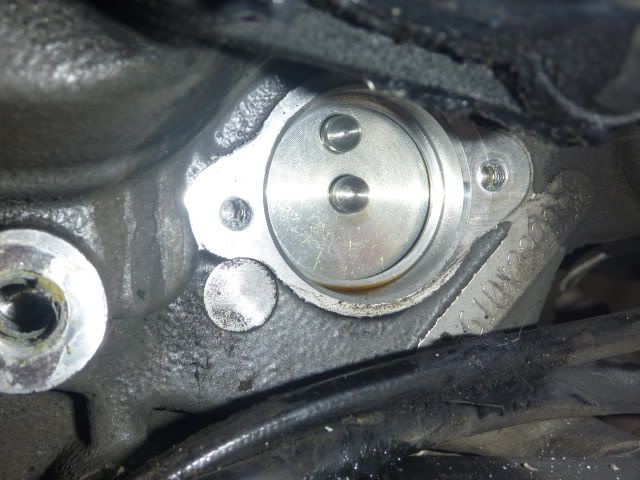
Here's where I got to last time. One photo shows the internal mechanism, the other the electrical contacts.
You'll notice that the electrical contacts have a small pickup for neutral and two others for second and third (I think).
My idea was to just drill and add more contacts (because the positions are indexed - ie entirely symetrical) then
design a circuit that sorts out the electrical signal (which contact is earthed) then convert it to binary coded decimal
which is what the driver for the LED chip needs 4511 from memory (at the ex's house)
My thinking was to put everything in the headlight shell other than a 6-8 strand cable down to the gear change pickup.
A resistance based system would work I guess. Keep in mind that the wires that come out of the switch itself are redundant
for most people (often disconnected) because it's just used as a performance limiter. Thus the switch can be made to
do anything you want. The world is your oyster. You could design a PIC based system but I'd be inclined to keep it
as simple (and cheap) as possible. As you can see the display is about $US5 so I'd want the whole thing to be about $US30 max.
I bet there are people that already have the electrical stuff done. All we need is something that could plug into the
gear change sensor hole to provide 6-7 signals (neutral as well).
Of course a much simpler idea is just to have a row of leds in which one would light up for each gear. I did in fact buy a spare mask
and the LED's but got bogged down with other things.